41 Wyniki
Wyświetl wyniki:
Sortuj według:
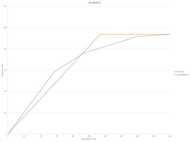
Aby można było przeprowadzić obliczenia push-over, należy zdefiniowaną krzywą nośności przekształcić do postaci uproszczonej. Tak zwana metoda N2 jest opisana w Eurokodzie EN 1998. Ten artykuł powinien pomóc w wyjaśnieniu, co oznacza bilinearyzacja zgodnie z metodą N2.
Wydarzenia ostatnich lat przypominają nam o znaczeniu konstrukcji odpornych na trzęsienia ziemi w zagrożonych regionach. Projektowanie konstrukcji na obszarach narażonych na trzęsienia ziemi jest ciągłym kompromisem między efektywnością ekonomiczną i możliwościami finansowymi, a także bezpieczeństwem. Jeżeli zawalenie jest nieuniknione, należy ocenić, w jaki sposób wpłynie ono na konstrukcję. Celem tego artykułu jest przedstawienie jednej z opcji przeprowadzenia tej oceny.
Programy do arkuszy kalkulacyjnych, takie jak EXCEL, są popularne wśród inżynierów, ponieważ można z łatwością zautomatyzować obliczenia i szybko uzyskać wyniki. Połączenie programu MS EXCEL jako graficznego interfejsu użytkownika z WebService API jest zatem oczywiste. Za pomocą bezpłatnej biblioteki xlwings dla Pythona można sterować programem EXCEL oraz odczytywać i zapisywać wartości. Funkcjonalność tę wyjaśniono poniżej na przykładzie.

Jakość analizy statyczno-wytrzymałościowej budynków jest dużo lepsza, gdy można uwzględnić warunki gruntowe w sposób możliwie najbardziej realistyczny. W programie RFEM 6 można realistycznie określić kontur glebowy do analizy za pomocą rozszerzenia Analiza geotechniczna. Ten dodatek można aktywować w danych bazowych modelu, jak pokazano na rysunku 01.

Obliczenia konstrukcji złożonych za pomocą oprogramowania do analizy elementów skończonych są zazwyczaj przeprowadzane na całym modelu. Jednak wznoszenie tego typu konstrukcji jest procesem wieloetapowym, w którym ostateczny stan konstrukcji uzyskuje się poprzez połączenie poszczególnych elementów konstrukcyjnych. Aby uniknąć błędów w obliczeniach ogólnych modeli, należy wziąć pod uwagę wpływ procesu konstrukcyjnego. W programie RFEM 6 jest to możliwe za pomocą rozszerzenia Analiza etapów budowy (CSA).
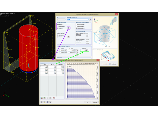
W celu przyłożenia obciążeń o zmiennej wysokości i obwodzie do obiektów obrotowo symetrycznych, program RFEM zapewnia swobodne obciążenie zmienne.
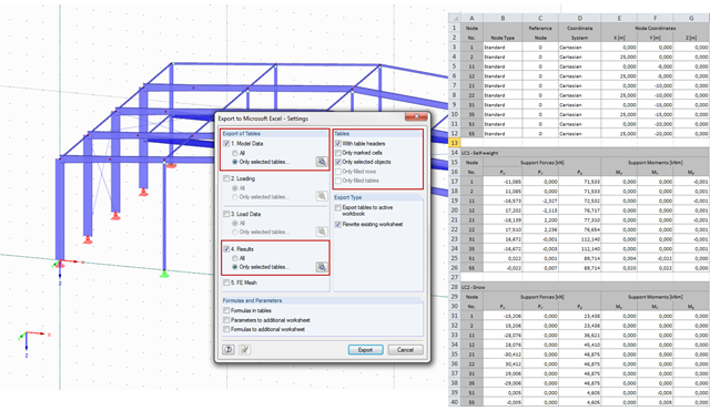
W programach RFEM i RSTAB można eksportować wyniki obliczeń do dokumentu Excel.
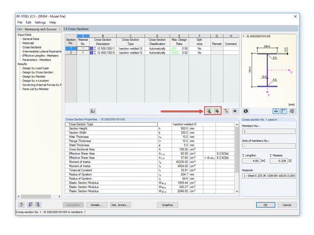
Mit RF-/STAHL EC3 ist es möglich, einen Querschnitt im Rahmen der Bemessung automatisch optimieren zu lassen. Dies erfolgt bei entsprechender Aktivierung in der Tabelle 1.3 auf Basis der aktuellen Profilreihe oder bei geschweißten Querschnitten im Rahmen der definierten variablen Parameter.
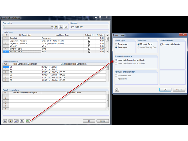
In RFEM und RSTAB ist es möglich, ein benutzerdefiniertes Kombinationsschema zu definieren. Może to być pomocne, jeżeli żądany schemat kombinacji nie może zostać utworzony według normy. Hierfür können die erstellten Lastfälle nach Excel exportiert, dort das Schema erstellt und nach RFEM beziehungsweise RSTAB importiert werden.
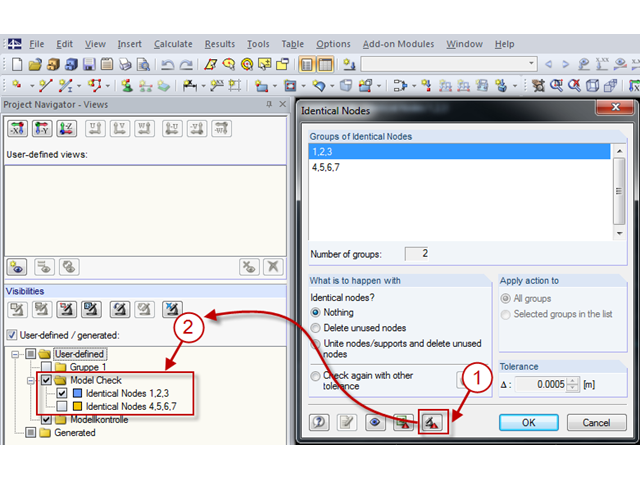
Mit der Modellkontrolle kann gezielt nach Unstimmigkeiten gesucht werden, die sich bei der Modellierung ergeben.
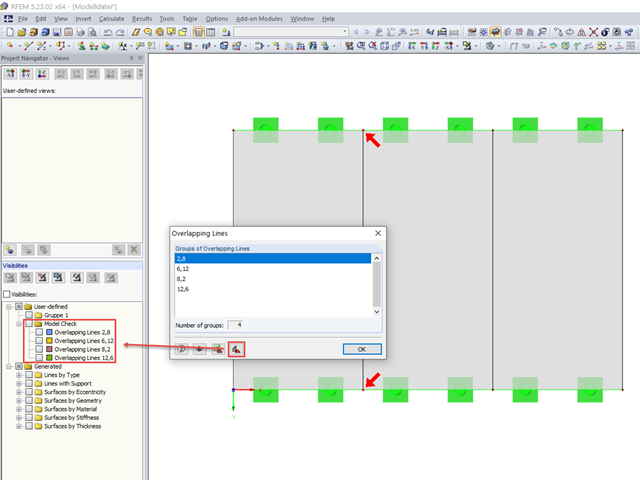
Mitunter können bei der Modellierung in RFEM doppelte Linien entstehen. Damit diese schneller gefunden und gegebenenfalls gelöscht werden können, ist es in RFEM 5 möglich, überlappende Linien zu exportieren. Dies ist beispielsweise nach Excel oder in eine eigene Gruppe der Ausschnitte möglich.
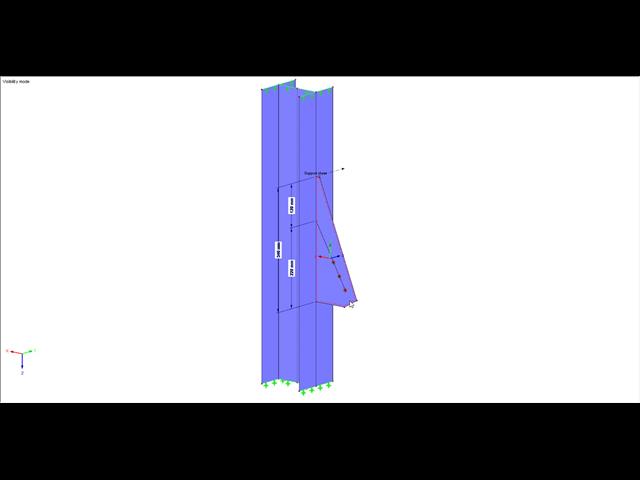
Europejska norma EN 1993-1-8, sekcja 4.5.3.3. umożliwia zastosowanie uproszczonej metody obliczania stanu granicznego nośności spoin pachwinowych. Zgodnie z normą warunki nośności można uznać za spełnione, jeżeli wartość obliczeniowa wypadkowej oddziałującej na obszar spoiny pachwinowej jest mniejsza niż wartość obliczeniowa nośności spoiny. Jeśli więc wymiarowanie spoiny ma zostać przeprowadzone na bazie wyników z modelu powierzchniowego, użytkownik może odczytać liczne typy rezultatów ze względu na charakter obliczeń MES dla powłok. Dlatego w tym artykule pokazujemy, jak określić składowe siły z takiego modelu.
Jeżeli żebro w stropie jest elementem konstrukcji obliczanej nieliniowo lub jest sztywno zamocowane w ścianach dochodzących, do jego modelowania należy użyć powierzchni zamiast pręta. Aby żebro nadal mogło być zaprojektowane jako element prętowy, należy zdefiniować belkę wynikową o prawidłowym mimośrodzie, która pozwala odczytać siły wewnętrzne w powłoce jako siły wewnętrzne dla równoważnego pręta.
.png?mw=640&hash=2cf2e90647c5387f6e549d5f51132b8034832f4b)
Poniżej opisano procedurę obliczania stanu granicznego użytkowalności płyty fundamentowej z betonu zbrojonego włóknami stalowymi. Zaprezentowano w jaki sposób przeprowadzić sprawdzenie SLS za pomocą iteracyjnie wyznaczonych wyników z analizy nieliniowej MES.
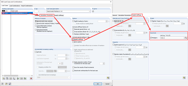
Zarówno analiza drgań własnych, jak i analiza spektrum odpowiedzi przeprowadzane są na układzie liniowym. Jeżeli w modelu występują nieliniowości, podlega on linearyzacji, dzięki czemu elementy nieliniowe nie są brane pod uwagę w dalszej analizie. W praktyce jednak bardzo często wprowadzamy do modeli elementy "tylko rozciągane". W przedstawionym artykule opisano, w jaki sposób można je poprawnie zastąpić dla przeprowadzenia liniowej analizy dynamicznej.
Stahlfaserbeton wird heutzutage vor allem für Industriefußböden beziehungsweise Hallenböden, gering beanspruchte Fundamentplatten, Kellerwände und Kellersohlen eingesetzt. Seit der Veröffentlichung der ersten DAfStb-Richtlinie Stahlfaserbeton im Jahre 2010 liegt dem Tragwerksplaner ein bauaufsichtlich eingeführtes Regelwerk für die Bemessung des Verbundwerkstoffes Stahlfaserbeton vor, wodurch der Einsatz von Faserbeton in der Baupraxis immer beliebter wird. W artykule tym opisano nieliniowe obliczenia płyty fundamentowej wykonanej z betonu zbrojonego włóknami stalowymi w stanie granicznym nośności, z wykorzystaniem oprogramowania RFEM.
.png?mw=640&hash=384433771bc14951c64cacfda2ebf4a56a9927e5)
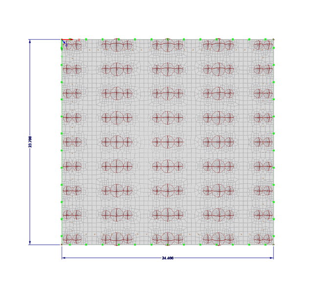
W artykule tym pokazano wpływ różnych sztywności ścian drewnianych na rzut.
.png?mw=640&hash=1be9a846b1f57190540c7fc7f46f44cd40ab7029)
Wenn man über die COM-Schnittstelle die Ergebnisse einer Fläche ausliest, so erhält man ein eindimensionales Feld mit allen Ergebnissen an den FE-Knoten oder Rasterpunkten. Aby uzyskać wyniki na krawędzi powierzchni lub wzdłuż linii wewnątrz powierzchni, należy odfiltrować wyniki w obszarze linii. Poniższy artykuł opisuje funkcję, jakiej można użyć w tym celu.
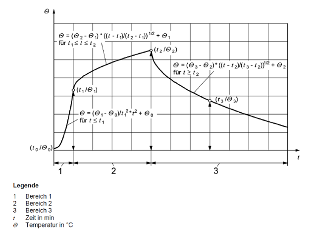
Moduł RF-/STEEL EC3 umożliwia korzystanie z nominalnych krzywych temperatura-czas w programach RFEM i RSTAB. Do modułu wprowadzono standardową krzywą temperatura-czas (ETK), krzywą pożaru zewnętrznego oraz węglowodorową krzywą pożaru. Ponadto, program zapewnia opcję bezpośredniego określenia końcowej temperatury stali.
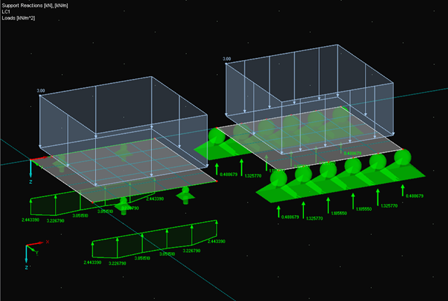
Podczas analizy sił podporowych dla linii, uzyskane wykresy czasem na pierwszy rzut oka wydają się nieprawdopodobne. W szczególności: w przypadku obciążeń zmiennych w miejscach, w których również znajdują się podpory węzłowe, w punktach podziału i na krawędziach linii podpartych wyniki czasami pokazują nieoczekiwane reakcje podporowe. Włączenie funkcji liniowego rozkładu gładkiego w Nawigatorze projektu - Wyświetlanie nie zawsze pokazuje spodziewany wykres wyników.
.png?mw=640&hash=6e011ea537587ceb48d9e642d642150a151c551e)
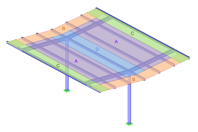
Norma ASCE 7-16 wymaga zastosowania zarówno zrównoważonych, jak i niezrównoważonych obciążeń śniegiem, do uwzględnienia w obliczeniach konstrukcji. Podczas gdy może to być bardziej intuicyjne w przypadku dachów płaskich, a nawet dwuspadowych/czterospadowych, określenie obciążeń śniegiem jest coraz trudniejsze w przypadku dachów łukowych ze względu na złożoną geometrię. Jednak dzięki wytycznych z ASCE 7-16 na temat obliczeń obciążenia śniegiem zakrzywionych dachów oraz efektywnym narzędziom RFEM do przypisywania obciążeń, możliwe jest uwzględnienie zarówno zrównoważonych, jak i niezrównoważonych obciążeń śniegiem w celu niezawodnego i bezpiecznego wymiarowania konstrukcji.
.png?mw=640&hash=116715fdcf1e482a2a75814f99d5be2c0a8259eb)
Modelowanie informacji o budynku pojawia się na pierwszych stronach gazet w projektowaniu budynków. Podczas gdy niektórzy inżynierowie używają tylko metod BIM do planowania, inni zajmują się tym tematem po raz pierwszy lub rzadko mają na to czas w swojej codziennej pracy. Jednak jeden temat wydaje się najważniejszy w inżynierii konstrukcyjnej: Jakie korzyści mogą odnieść inżynierowie budowlani z BIM?
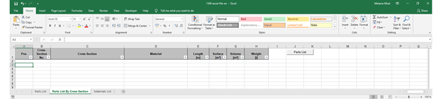
Stücklisten geben Auskunft darüber, welche und wie viele Teile für die Erzeugung eines Bauwerks benötigt werden. Sie bilden somit die Basis für die Bedarfsermittlung und Beschaffung. Stücklisten können in den Bemessungsmodulen wie RF-/STAHL EC3, RF-/HOLZ Pro et cetera erstellt werden. Eine auf die Bedürfnisse des Anwenders zugeschnittene Stückliste kann darüber hinaus mit der Schnittstelle RF-COM/RS-COM programmiert werden.
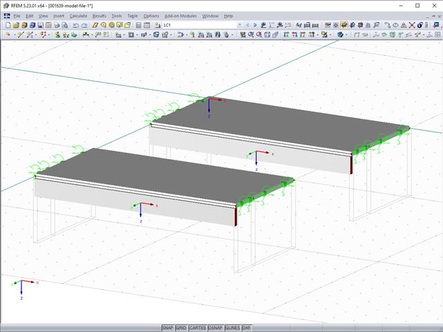
Jeżeli istnieje konieczność zaprojektowania zadaszenia np. stacji benzynowej, konieczne jest zdefiniowanie obciążenia zgodnie z EN 1991-1-4, Sekcja 7.3. Niniejszy artykuł pokazuje przykładowe wymiarowanie dachu z blachy trapezowej, o lekkim nachyleniu.
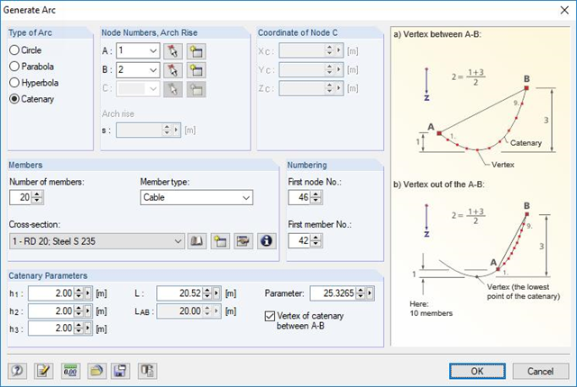
RFEM und RSTAB können als Vertreter der allgemeinen Stab- beziehungsweise FEM-Programme eine Vielzahl von Teilgebieten des Bauwesens abdecken. So ist auch die Bemessung von Seiltragwerken in beiden Software-Lösungen möglich. Im Folgenden sollen einige Modellierungs- und Bemessungshilfen vorgestellt werden.
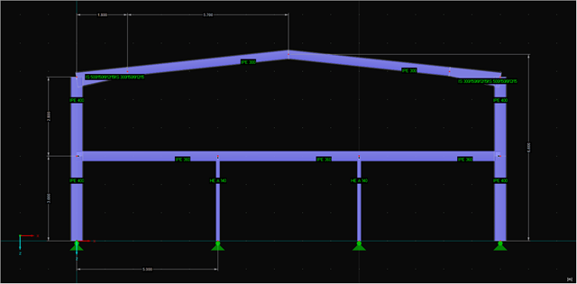
![Układ konstrukcyjny i wymiary przekroju według [1]](/pl/webimage/009153/482068/01-de.png?mw=640&hash=9f6ca6566391e0348354d64018782d9ffd5f7c70)
Istnieje kilka opcji obliczania półsztywnej belki zespolonej. Opcje te różnią się głównie sposobem modelowania. Podczas gdy metoda Gamma zapewnia proste modelowanie, w przypadku stosowania innych metod (np. analogia ścinania) do modelowania wymagane są dodatkowe nakłady pracy, które są jednak równoważone przez znacznie bardziej elastyczne zastosowanie w porównaniu z metodą Gamma.
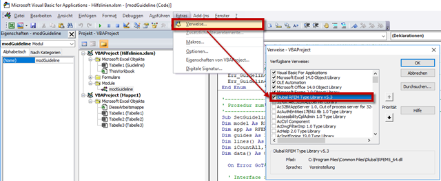
RF-COM/RS-COM to programowalny interfejs, który umożliwia rozszerzenie programów głównych RFEM i RSTAB o niestandardowe makra wejściowe lub programy do obróbki końcowej. W artykule tym zostanie opracowane narzędzie do kopiowania i przenoszenia wybranych linii pomocniczych w programie RFEM. Można też skopiować lub przenieść linie pomocnicze na inną płaszczyznę roboczą. Jako środowisko programistyczne zostanie wykorzystane VBA w Excel.

Das eigenständige Programm DUENQ ermittelt die Kennwerte und Spannungen für beliebige dünnwandige Querschnitte. Grafische Tools und Funktionen ermöglichen die Modellierung von komplexen Querschnittsformen. Oprócz wprowadzenia danych graficznie, można je wprowadzić za pomocą tabel. Alternatywnie istnieje możliwość importu pliku DXF i wykorzystania go jako szablonu do dalszego modelowania. Ebenfalls kann jeder Querschnitt aus der Dlubal-Querschnittsbibliothek eingegeben und als Teil mit den vom Benutzer definierten Elementen kombiniert werden.
Rozdziały 4.1 i 4.2 tej serii artykułów opisują optymalizację konstrukcji szkieletowej z wykorzystaniem modułu dodatkowego RF-/STEEL EC3. Der fünfte Teil deckt dabei die Anbindung des Moduls und das Holen relevanter Stäbe ab. Auf die Elemente, welche in vorangegangenen Teilen bereits erläutert wurden, wird nicht nochmal eingegangen.
W części 2.2 serii artykułów na temat interfejsu COM opisano tworzenie i modyfikowanie podpór węzłowych, obciążeń, przypadków obciążeń, kombinacji obciążeń i kombinacji wyników na przykładzie pręta. W czwartej części wyjaśniono tworzenie poszczególnych narzędzi.